

Dimensioning and Notes

Presentation
•
Design
•
9th Grade
•
Practice Problem
•
Medium

Tammie Holland -Stamm
Used 13+ times
FREE Resource
56 Slides • 7 Questions
1
Dimensioning and Notes
2
Word Cloud
Why do we need dimensions?
3
Why Are They Important?
They provide the complete information manufacturers need to bring the designer's vision to life and ensure proper fit, function, and compliance with specifications.
4
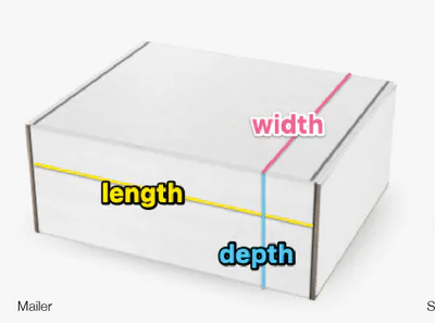
Precise measurements (length, width, height, diameters, tolerances) for accuracy.
Dimensions
5

Additional instructions such as:
Material specifications
Surface finishes
Assembly instructions
References to industry standards
Shop Notes
6
Other Critical Information
Tolerances for allowable variations.
Multiple views for clarity (e.g., top, front, side, or sectional).
Standard symbols for machining, threads, welds, etc.
7
Answer:
Dimensions and shop notes are needed if an object is to be manufactured according to the designer's specifications, ensuring accuracy and functionality.
8
Dimensions: Define the sizes of the geometrical features of an object.
Notes: Provide additional information not conveyed through dimensions.
Purpose of Dimensions and Notes
9
Answer:
the sizes of the geometrical features of an object
10
Answer:
additional information not included in the dimensions.
11
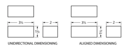
Unidirectional Dimensions:
Placed to read from the bottom of the drawing.
Aligned Dimensions:
Placed parallel to the dimension line.
Numerals are read from:
The bottom of the drawing.
The right side of the drawing.
How Dimensions are Placed
12
How Dimensions are Placed
13
Notes and Leaders
All dimensions shown with leaders and notes are lettered parallel to the bottom of the drawing, regardless of the dimensioning method used.
14
Answer:
the bottom of the drawing.
15
Answer:
the bottom and right side of the drawing.
16
Dimension Lines:
Fine solid lines indicating distance and location.
Broken for insertion of dimensions.
Capped with arrowheads for clarity.
Key Elements of Dimensioning
17
Extension Lines:
Extend out from the drawing without touching it.
Project 1/8 in. (3.0 mm) beyond the last dimension line.
Key Elements of Dimensioning
18
Dimension Placement
Smaller or Detail Dimensions: Placed nearest the view.
Larger or Overall Dimensions: Placed farthest from the view.
Key Elements of Dimensioning
19
20
Multiple Choice
6. The dimension line is a _________?
heavy solid line
fine solid line
fine dotted line
none of the above
21
Fill in the Blanks
The dimension line is capped with
22
Placement: Place dimensions on views showing the true shape of the object.
Avoid Crowding: Avoid placing dimensions within views unless necessary.
Grouping: Group dimensions together; avoid scattering across the drawing.
Completeness: Ensure all dimensions are complete to eliminate the need for scaling.
Key Rules for Clarity and Accuracy
23
Direction: Draw dimension lines parallel to measurement, staggering numerals for readability.
No Duplication: Avoid duplicating or including unnecessary dimensions.
Avoid Crossings: Plan to prevent dimension lines from crossing extension lines.
Key Rules for Clarity and Accuracy
24
Units:
Inches: Omit the inch symbol (") when all dimensions are in inches.
Metric: Use millimeters unless noted otherwise.
Numerals: Write numerals and fractions with proper proportionality and alignment.
Key Rules for Clarity and Accuracy
25
26
Fill in the Blanks
Dimensions are placed on views that show
27
Answer:
Dimensions should be grouped together rather than scattered about the drawing.
28
Multiple Choice
Dimensions must be complete so that _______.
no scaling of the drawing is necessary
sizes and shapes can be determined without assuming any measurements
All of the above
None of the above
29
Answer:
When all dimensions are in inches, the inch symbol (") is not used.
30
Circles and Holes:
Use the Greek letter φ (phi) to indicate a diameter, placed before the dimension.
If unclear that a hole goes through, add THRU after the dimension.
Specify hole depth and features like spotfacing, counterboring, or countersinking with symbols.
Key Guidelines for Dimensioning
31
Arcs:
Dimension by specifying the radius (R), with "R" placed before the dimension.
Concentric Circles:
Dimension diameters on the front view for clarity.
Key Guidelines for Dimensioning
32
Leader Lines:
Always point to the center of the diameter or arc.
Cylindrical Parts:
Dimension from the centers, not the edges.
Key Guidelines for Dimensioning
33
Series of Holes:
Use a note to indicate:
Number of holes
Their size
The diameter of the circle on which they are located
Key Guidelines for Dimensioning
34
35
Answer:
The circle diameter is indicated by the symbol φ. It is placed before the dimension.
36
Match

Label each letter symbol with the correct term.
A
B
C
D
Diameter
Hole Depth
Countersunk Hole
Counterbored or spot-faced hole.
Diameter
Hole Depth
Countersunk Hole
Counterbored or spot-faced hole.
37
Fill in the Blanks
When a leader is used to indicate a diameter, it always points to the
38
Angular dimensions are expressed in:
Degrees (°)
Minutes (')
Seconds (")
Key Guidelines for Dimensioning
Example - An angle might be dimensioned as 45° 30' 15", indicating:
45 degrees 30 minutes 15 seconds
39
When the space between extension lines is too small for both numerals and arrowheads
Numerals are placed outside the extension lines.
Arrowheads point to the dimension lines from outside the space.
Why This Matters
This approach maintains clarity and ensures that dimensions remain legible, even in tight spaces, while adhering to drafting standards.
Key Guidelines
40

41
Metric Measurements: Widely used internationally to improve competitiveness.
Transition Challenges:
Difficulty interfacing metric-designed parts with inch-standard parts at interfaces (joining surfaces).
Collaboration: Industries working together must use the same measurement system to avoid inconsistencies.
Key Insights
42
Dual Dimensioning: Includes both metric and conventional measurements.
Letters and Tabular Chart: Dimensions represented with reference letters tied to a chart.
Metric Dimensioning with Readout Chart: Metric dimensions supported by a chart for conventional equivalents.
Metric Units Only: Dimensions provided exclusively in metric units.
Undimensioned Master Drawings: Rely on undimensioned drawings as a reference, often used with digital models.
Five Methods for Managing the Transition
43
44
A method of dimensioning engineering drawings with both inch and metric units.
Used to facilitate the transition between measurement systems.
Placement Rules
Inch Dimension First: For drawings produced in the United States.
Metric Dimension First: For drawings produced where metric is standard.
What is Dual Dimensioning?
45
A technique where letters (A, B, C, etc.) replace inch or millimeter dimensions.
A tabular chart accompanies the drawing, listing the metric and inch equivalents for each letter.
Key Advantages
Simplifies the drawing by reducing clutter.
Allows for easy comparison of metric and inch dimensions.
What is it?
46
Replace the dimensions on the drawing with corresponding letters.
Include a tabular chart with the drawing:
Matches each letter with its metric and inch equivalents.
How it works
47
Answer:
Dual dimensioning is a method of presenting measurements on engineering drawings using both inch and metric units to accommodate different measurement systems. It is displayed using either the position method (one above the other) or the bracket method (dimensions in brackets).
48
Answer:
The person using the drawing gets the inch/millimeter sizes from the tabular chart included with the drawing.
49
A method where parts are designed to metric standards with only metric dimensions on the drawing.
A readout chart is added to show metric values and their inch equivalents.
How it Works
Metric Dimensions: Placed on the drawing.
Readout Chart:
Left column: Metric dimensions.
Right column: Inch equivalents.
What is it?
50
A method of dimensioning where only metric units are used on the drawing.
Why Use It?
Encourages engineers, designers, drafters, and craftworkers to "think metric."
Simplifies the drawing by eliminating the need for conversions or dual measurements.
Advantages
The quickest method to adopt metric standards.
Reduces confusion by focusing solely on one measurement system.
What is it?
51
Master Drawing: Created without dimensions.
Customized Prints:
Metric dimensions added to one print.
Inch dimensions added to another.
Notes and details adapted for various languages (e.g., German, French, English, Japanese).
What are Undimensioned Master Drawings?
52
Allows flexibility for international production.
Reduces clutter in the original master drawing.
Key Considerations
Scales and Templates: Drafting personnel must have tools for both metric and conventional systems.
Metric Knowledge: A thorough understanding of the metric system is essential.
Why Use This Method?
53
Metric and inch systems are not always interchangeable:
No exact metric equivalent for some imperial sizes (e.g., 9/16 in. or 1.0 in.).
Custom machining may be required, increasing costs.
Challenges
54
Answer:
A master drawing is a technical drawing created without dimensions. It serves as a base for creating multiple customized prints. Metric dimensions can be added to one print, inch dimensions to another, and notes can be tailored to different languages as needed for production. This approach allows flexibility for global collaboration and simplifies the adaptation of designs for various standards and languages.
55
Standard Unit:
The millimeter (mm) is the standard unit for dimensioning engineering drawings.
Decimal Format:
Use one-place decimals for most dimensions (e.g., 125.0).
Two or three decimal places are used for critical tolerances.
Full millimeter dimensions include a zero to the right of the decimal (e.g., 125.0).
Key Rules
56
Dimensions Less than 1 mm:
A zero must precede the decimal point (e.g., 0.5, not .5).
Identification of Metric Drawings:
Include a note on the drawing:
"All dimensions are in millimeters."This eliminates the need to add "mm" after every dimension.
Key Rules
57
Spacing with Symbols:
A space must be placed between the dimension and the "mm" symbol:
Correct: 125.0 mm
Incorrect: 125.0mm
Key Rules
58
A precise system for specifying dimensions and tolerances on technical drawings.
Ensures accuracy in form, profile, orientation, location, and runout of features.
Standardized for global manufacturing and interchangeable parts.
What is GD&T
59
Geometric Characteristic Symbols:
Define tolerances for shape, position, and relationship of features.
Datums:
Exact points, axes, planes, or surfaces used as references for locating features.
Identified by letters in boxes, attached to triangles or dimension lines.
Key Features
60
Feature Control Frame:
A rectangular box divided into compartments containing:
Characteristic symbols.
Allowable tolerance.
Datum reference letters.
Positioned alongside dimensions or extension lines.
Key Features
61
Provides an international standard for communication.
Facilitates precision and economy in manufacturing.
Ensures compatibility when parts are made in different locations.
Why Use GD&T
62
Answer:
A highly precise system of specifying dimensions and tolerances on drawings is called Geometric Dimensioning and Tolerancing (GD&T).
63
Answer: datum
A datum is a reference feature used in geometric dimensioning and tolerancing (GD&T) to precisely locate and align other features of a part. It can be a point, axis, plane, or surface that serves as a starting point for measurements and defines the exact location or orientation of features in a consistent and repeatable way.
For example:
A point datum might be used to locate the center of a circular feature.
An axis datum could align cylindrical features.
A plane datum might define a flat surface as a baseline for other measurements.
Datums are critical for ensuring consistency and accuracy in manufacturing, especially when parts are made in multiple locations or need to fit together perfectly with other components.
Dimensioning and Notes
Show answer
Auto Play
Slide 1 / 63
SLIDE
Similar Resources on Wayground

61 questions
Algebra 1 Part 1 Regents June 2022
Presentation
•
9th Grade
60 questions
The Constitution
Presentation
•
9th - 10th Grade
57 questions
Exploring Patterns Everywhere
Presentation
•
9th Grade
53 questions
Understanding and Writing ECR
Presentation
•
9th Grade
56 questions
Africa Map 2
Presentation
•
9th Grade
58 questions
4.1 Bonding Notes
Presentation
•
9th Grade
59 questions
資訊科技的社會議題
Presentation
•
8th Grade
56 questions
Measurement, Motion & Density
Presentation
•
9th Grade
Popular Resources on Wayground
10 questions
Safety Day 2026 – Student Review

Quiz
•
9th Grade
21 questions
Continents and Oceans
Quiz
•
6th Grade
20 questions
Parts of Speech
Quiz
•
5th Grade
16 questions
Subject & Predicate
Quiz
•
5th Grade
25 questions
Multiplication Facts
Quiz
•
5th Grade
12 questions
Map Skills
Quiz
•
3rd Grade
22 questions
Continents and Oceans
Quiz
•
5th Grade
15 questions
Rounding Decimals
Quiz
•
5th Grade
Discover more resources for Design
10 questions
Safety Day 2026 – Student Review
Quiz
•
9th Grade
20 questions
REGULAR Present tense verbs
Quiz
•
8th - 9th Grade
26 questions
SLIME!!!!!
Quiz
•
KG - 12th Grade
10 questions
Test Your Knowledge on Bullying
Quiz
•
9th Grade
12 questions
Absolute Value Equations
Quiz
•
9th Grade
20 questions
Position vs. Time Graphs
Quiz
•
9th Grade
20 questions
Function or Not a Function
Quiz
•
8th - 9th Grade
10 questions
Exploring Chemical and Physical Changes

Interactive video
•
6th - 10th Grade